How exhaust gas dynamics work
- Good Fabrications Ltd
- Jan 15, 2017
- 3 min read

If you want to improve the power output of your engine, you need to take into account the exhaust dynamics and how the exhaust can be tuned to the engine.
In this article, the basic exhaust dynamics in a four stroke spark ignition engine are briefly discussed with a focus on the basics of exhaust gas dynamics.
The Four Stroke Process
A four-stroke engine is an internal combustion (IC) engine in which the piston completes four separate strokes.
The first stroke is the intake stroke, where the piston of the engine travels down while there is an open intake valve. This allows the fresh air and fuel to fill the cylinder.
When the piston is at the bottom, the valve closes and the piston moves up again while compressing the fresh air and fuel mixture.
When the piston is at the top, a spark plug ignites the mixture, causing an explosion inside the cylinder, with both valves completely closed, which pushes the cylinder back down again while the burning gasses are expanding.
When the piston reaches the bottom again, this time the exhaust valve opens allowing the exhaust gases to escape the cylinder while the piston moves up and pushes them out.
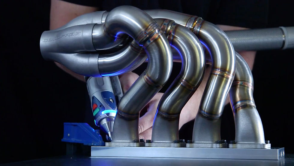
From here they travel in the exhaust manifold’s tubes, allowing them to escape and leave room for a new fresh charge through the induction system.

The Gas Dynamics
When the exhaust gases travel out of the cylinder, they have a relatively high speed and pressure.
The speed of the exhaust gas moving through the tubes of the manifold is different than the speed of the pressure waves created by this movement.
These pressure waves travel through the exhaust manifold at the local speed of sound which can be over 500m/s in that environment, while the gases themselves move at an average speed of about 100 – 125m/s.
If the manifold is not designed properly, this can lead to a large back pressure in the exhaust system and have a negative effect on efficiency resulting in a decrease of the power output.
When the pressure waves reach a change in geometry, a negative pressure wave is generated in the opposite direction.
If not timed correctly, these negative pressure waves could restrict the flow of the exhaust gas out of the cylinder.
If this negative pressure wave is timed properly, taking into account all the variables in an exhaust system, this wave can help scavenge (draw the exhaust gas out) the cylinder and create a lower pressure in the cylinder causing the intake charge to be drawn into the cylinder better.
Using a single non variable geometry exhaust pipe, one would think there would be only one occasion where the negative pressure wave is beneficial for the charging of the cylinder. However, that is not always the case.
In many applications multiple step rings are used to create different resonance peaks at different engine speeds.

Since the pressure waves resonate in the exhaust system, there would be occasions where the traveling of an already reflected wave creates a new negative pressure wave. This new wave would be less powerful, but could still be beneficial for the scavenging process.
The effect and strength of the resonating pressure waves in the exhaust system are mainly driven by the initial pressure and the area change at geometry changes.
When using a smooth transition, the effect of these resonating waves will be less than using a step ring or a collector.
These are different resonance peak orders, and will reach the valve overlap at different engine speeds.
When designing an exhaust manifold, many variables need to be taken into account. Luckily nowadays there are plenty of simulation software packages but often we still see that the majority of the calculated geometries are still being verified on a trial and error basis on a dyno.


