.jpg)
How to optimize battery cooling?
- Dec 24, 2020
- 3 min read
At Goodfabs we have over 20 years of experience developing exhaust systems for the highest performing motorsport series such as Formula 1, Nascar, Indy and many others.
During these many years we have perfected our skills to form the thinnest walled materials to the highest precision.
The last couple of years we have been a successful part of the change from the natural aspirated engines to the turbocharged engines and now, with the new era of EV high performing motors, Goodfabs are working again to be pioneers in perfecting the cooling systems for the latest power source.
The main power of the EV motorsports are drawn from the battery packs. During the races and accelerations there is a very high power demand from the battery cells. At this time, the temperature of the cells increases consistently during which the power output can decrease or the cells could degrade.
If the temperature is not kept to the optimum operating temperature, the power output would be limited reducing the overall performance of the car.
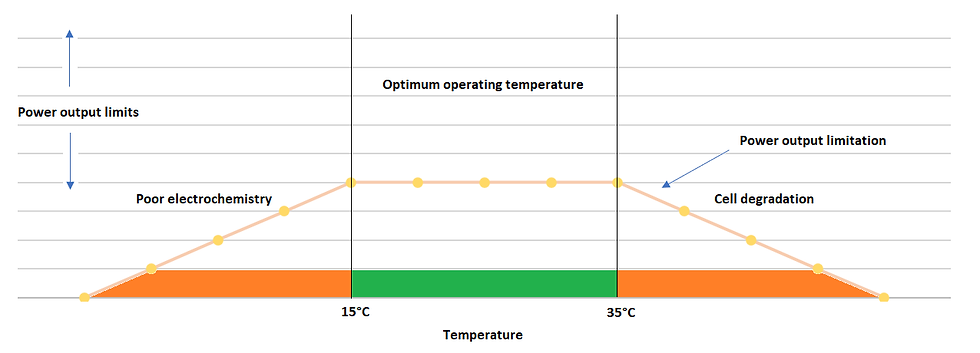
Image of a general 18650 Li-Ion cell temperature power output limitation
Creating a cooling system to ensure the cells are held at the optimum operating temperature range can be quite challenging, but at Goodfabs we have managed to obtain some very good results.
Challenges of the cooling channel geometry.
As with most of our projects, unfortunately we cannot disclose all the details. Luckily some projects we can share and we are always happy to do so! For this particular project we were using cylindrical 18650 cells (prismatic and flexible cells are also available, but come with their own limitations). Since the electrodes and separators in the cylindrical cells are rolled together, there is a risk for uneven temperature distribution during the discharging or charging cycles, meaning the outer surfaces need to be cooled as much as possible to maintain a relatively uniform temperature distribution over the cells walls.
This meant one key aspect of this development was the fact that the battery cells needed to be cooled as much as possible on the outer surfaced. Since these are cylindrical and packed very tightly together, this did not leave us much room to create the cooling system, as the cooling liquid is not allowed to be in contact with the cells, this proved out to be a challenge.
Secondly by offsetting the cylindrical cells, a lot of space is gained and more cells can be placed in the battery cell pack, meaning more power output is possible.

Image of formed MPE battery cell pack cooling channel
This however put the bar even higher, as this did not only reduce the amount of space where we could work in, but also added the dimension of having a fully curved cooling circuit. At the same time, the circuit needs to be fairly rigid and provide enough cross sectional area to allow for a good cooling flow.
Cooling channels
After some initial developments and trials, we quickly discovered that a multiport extrusion (or microport extrusion) or also called MPE could be ideal to guide the cooling liquid through the cells. The MPE has inner channels to ensure a continuous flow throughout the entire height of the channels.
Tailored forming and fabrication process
The forming of MPE channels requires a precision process to ensure the internal microchannels do not collapse or are deformed. By using multiple step forming processes the accuracy of the forming while maintaining the shape of the inner channels is achieved.
In the Goodfabs workshop we have access to the a large variation of presses such as hydraulic presses, fly presses, brake presses etc.
Next to these our 3, 4 and 5 axis CNC machining and turning centres, 3D printing capabilities (nylon, aluminium, titanium, Inconel,) enable us to create the intricate shapes often needed to fit the tightest areas these battery packs need to fit in.

Image of forming MPE multiport extrusion battery cell pack
Using 3D printing as micro solutions
Sometimes the area we can work in is so limited that the MPE channels cannot be extruded. This is often the case when the required flow volume of the cooling liquid is close to the actual area which we can work in. This often causes the need for very thin walled materials which cannot be extruded through the MPE moulds. To overcome this, we were able to successfully 3D print these MPE sections with wall thicknesses as little as 0,2mm and still remaining rigid and strong enough.
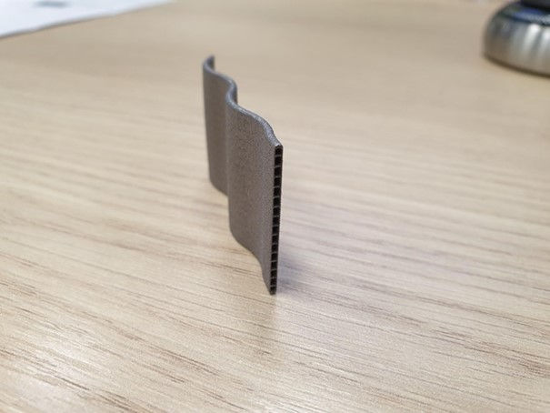
Image of 3D printed MPE multiport extrusion battery cell pack
Specific requirements
Since every single one of these systems come with its own challenges, it is important to consider the various methods of fabrication and welding during the design stage.
If you have any requirements, feel free to contact us at info@goodfabs.com.

